
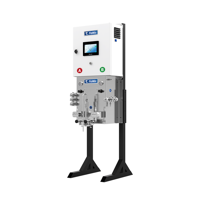
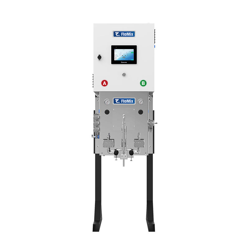


Why Choose the FloMix Proportioner
Every function of the system serves one purpose: the blend at the gun stays on-ratio, at the ratio you set.
● Plug-and-play integration — control unit, fluid panel and fluidics are pre-assembled on one frame; commissioning is power, air and paint connections only.
● Recipe-driven ratio accuracy — the mix ratio is entered on the HMI as a recipe, and the system verifies ratio accuracy against the flow meters on every dose. Changing to another ratio or coating is a recipe change, not a mechanical re-setting.
● One-touch flush and purge — a single command flushes and purges the dosing and color-change valves, the flow meters, the fluid lines and the gun, cutting color-change time and solvent use.
● Automatic color change built in — 1, 3 or 5 color positions per side, with the A and B sides configured independently, so a multi-color line needs no separate color-change manifold.
● Recirculating valve seats — the seat recirculation design lets coating circulate at the color-change valve, slowing pigment settling in the supply line.
● Sampling valves for ratio checks — the standard sampling valve manifold lets you draw a sample to calibrate the flow meters and perform ratio checks on the spot, without dismantling the system.
● Wear-resistant valve design — wetted parts in 316 stainless steel, PTFE and tungsten carbide; valve seats in tungsten carbide with SUS316 bodies; valve life of 1,000,000+ cycles depending on the coating.
System Layout: Controller, Fluid Panel and Mix Manifold
FloMix is built from six functional modules, all mounted on a single frame.
● 1. Main control unit — HMI touchscreen with recipe storage; sequences pumps, dosing valves and flush cycles.
● 2. Gun trigger signal interface — takes the trigger signal from the spray gun or the line controller, so proportioning and flush follow the actual spraying cycle.
● 3. A-side proportioning and color-change module — base (A) side, with its own flow meter and color positions.
● 4. B-side proportioning and color-change module — catalyst (B) side, configured independently of the A side.
● 5. 50 cc mix manifold — pre-mix chamber plus static mixer, mounted at the outlet of the two proportioning modules.
● 6. Gear flow meters — fitted as standard on both sides for closed-loop ratio control.
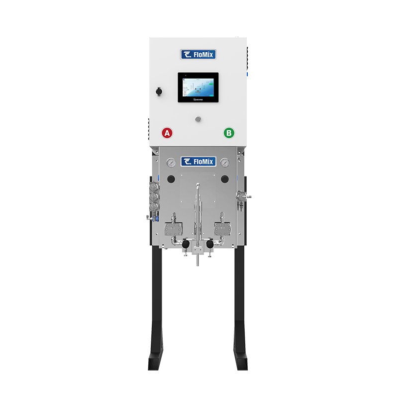
FloMix system frame — side view with dosing valves and mix manifold
Automatic Color Change: 1, 3 or 5 Colors
Color capacity is chosen per side, so the A and B sides do not have to match. Each module carries its colors plus one dedicated flush position, and color changes run as an automated flush-and-load sequence.
● Available as 1 color + 1 flush, 3 colors + 1 flush, or 5 colors + 1 flush.
● Double-acting cylinders give fast valve response at color change.
● Seat recirculation design lets coating circulate at the color-change valve, reducing settling.
● Wetted parts in 316 stainless steel, PTFE and tungsten carbide.
● Valve seats in tungsten carbide with SUS316 bodies for reliability and long service life.
● Precision-machined color-change valves rated for 1,000,000+ cycles, depending on the coating.
● Quick-release construction — color positions can be added or removed as the coating schedule changes.
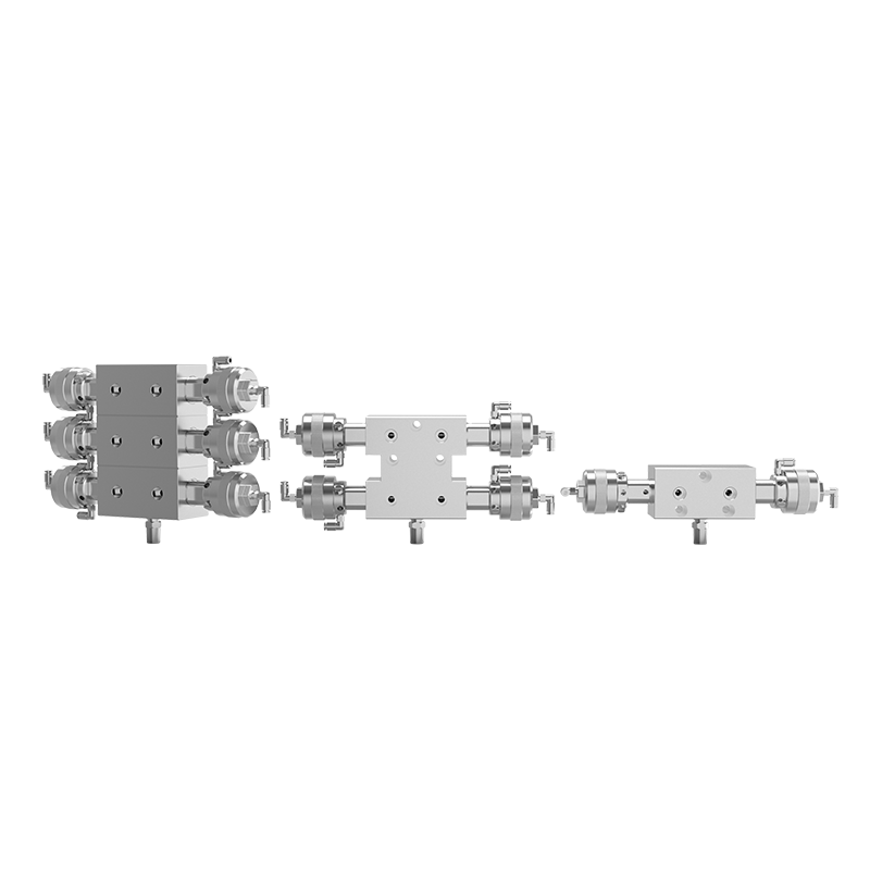
Proportioning and color-change valve modules — 1, 3 and 5 colors plus one flush position
Flow Meter Options: Gear Meters and Mass Flow Meters
Both sides can be fitted with gear flow meters or mass flow meters, in any combination.
● Gear flow meter (standard) — 5 – 3000 cc/min measuring range, compact and light, high-precision dual-bearing gear meter design, suitable for many material types, economical.
● Mass flow meter (optional) — straight-through bore with no moving parts in the flow path, high accuracy, measures mass flow, volumetric flow, density and temperature, wide material compatibility, higher cost.
Mix Manifold: 50 cc Pre-Mix Chamber and Static Mixer
The mix manifold combines a 50 cc pre-mix chamber with a static mixing element in one block mounted directly below the proportioning modules.
● A and B inlets each carry a sampling valve for flow calibration and ratio checks.
● Pre-mix chamber and static mixer in series give a homogeneous blend at the mixed material outlet, with no external mixing line.
● The static mixer element is a replaceable stainless-steel wear part.
● Mixed material outlet connects directly to the spray gun or to the line's gun manifold.
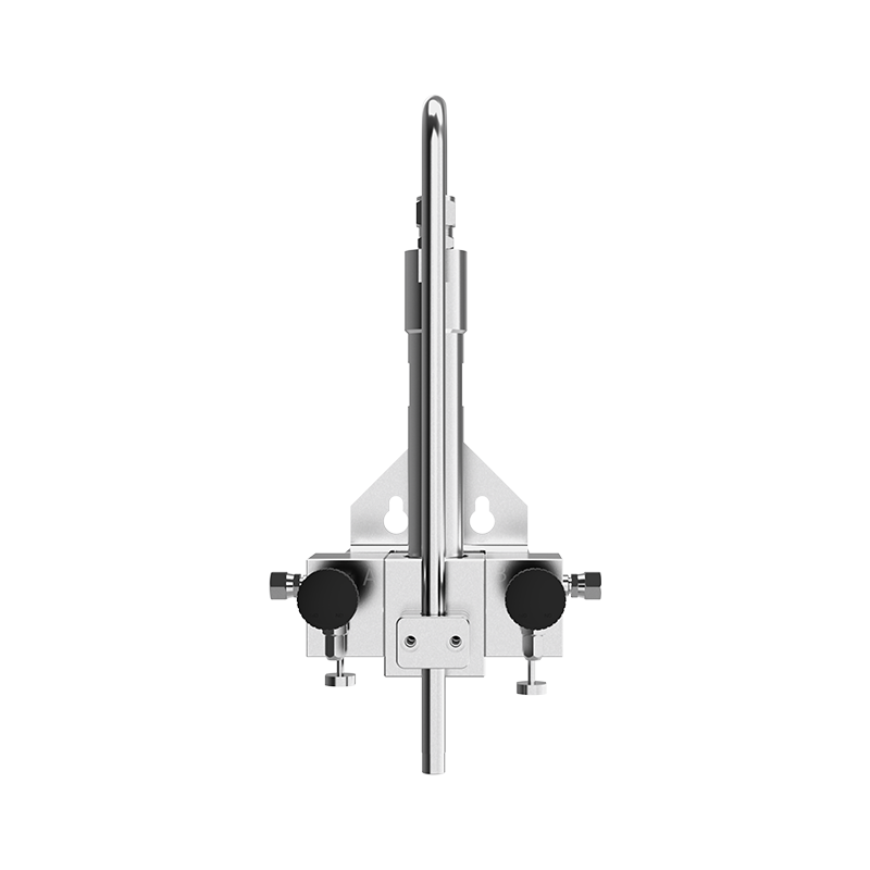
50 cc mix manifold with static mixer and A/B sampling valves
Applications: 2K and Plural Component Coating Lines
FloMix is specified for two-component coating lines in general industrial finishing, including electrical equipment and transformer coating lines.
● Manual spray stations — the HMI and the gun trigger interface let an operator proportion and flush from the booth.
● Automatic and robotic lines — the trigger signal interface ties proportioning and flush to the line controller, for air spray and high-pressure spray.
● Coating types — solventborne coatings, waterborne coatings, acid-catalyzed coatings and clearcoats, 20 – 5000 cps.
● Typical industries — electrical equipment and transformers, automotive parts, rail transit, construction machinery, 3C electronics, wood furniture.
Technical Specifications
Ratings below apply to the standard FloMix configuration. Confirm the paint supply pump and flow meter selection against your coating and flow demand before ordering.
|
Maximum fluid pressure, low-pressure system |
100 psi (7 bar, 0.7 MPa) |
|
Maximum fluid pressure, high-pressure system |
2900 psi (200 bar, 20 MPa) |
|
Maximum air pressure |
100 psi (7 bar, 0.7 MPa) |
|
Mix ratio range |
1:1 – 30:1, adjustable, ±1% mixing accuracy |
|
Flow range |
20 – 3000 cc/min |
|
Coating viscosity range |
20 – 5000 cps |
|
Noise level |
< 75 dB (A) |
|
Power supply |
AC 220 V, 50 – 60 Hz, 4 A |
|
Operating temperature |
5 – 50 °C (41 – 122 °F) |
|
Dimensions (reference) |
1200 mm × 800 mm × 1650 mm |
|
Suitable fluids |
Solventborne and waterborne coatings, acid-catalyzed coatings, clearcoats |
|
Wetted materials |
316 stainless steel, FFKM, PTFE |
Ordering Information
FloMix is configured with a five-part model code, F – paint supply pump – A-side flow meter – A-side color positions – B-side flow meter – B-side color positions.
|
Code position |
Option |
Description |
|
Paint supply pump |
0 |
No pump — system fed from an existing supply |
|
Paint supply pump |
L |
Base supply pump, low pressure |
|
Paint supply pump |
H |
Base supply pump, high pressure |
|
Flow meter, A side and B side (each) |
0 |
No flow meter |
|
Flow meter, A side and B side (each) |
1 |
Gear flow meter |
|
Flow meter, A side and B side (each) |
2 |
Mass flow meter |
|
Color positions, A side and B side (each) |
1 |
1 color + 1 flush |
|
Color positions, A side and B side (each) |
2 |
2 colors + 1 flush |
|
Color positions, A side and B side (each) |
3 |
3 colors + 1 flush |
|
Color positions, A side and B side (each) |
4 |
4 colors + 1 flush |
|
Color positions, A side and B side (each) |
5 |
5 colors + 1 flush |
Wear Parts and Replacement Parts
|
Part number |
Description |
|
CV3000 |
Proportioning and color-change valve |
|
DK0035 |
Proportioning valve solenoid |
|
JJ0025 |
High-pressure valve base |
|
JJ0026 |
Valve base gasket |
|
WJ003 |
Static mixer element, stainless steel |
|
LJ0005 |
Mix manifold check valve |
|
LT0012 |
A-side gear flow meter |
|
LT0002 |
B-side gear flow meter |